In industrial automation, the reliability of power modules can mean the difference between seamless production and costly, unplanned downtime. The FS450R12KE3/AGDR-71CS is a high-performance IGBT module widely used in demanding drive and inverter applications, where consistent power delivery is non-negotiable. Yet even the most robust components require disciplined maintenance to deliver peak performance over their operational lifespan.
Maintenance technicians working with industrial power systems frequently encounter challenges that range from subtle voltage irregularities to sudden module failures that halt entire production lines. Without a structured approach, diagnosing these issues can be time-consuming and expensive. The pressure to restore operations quickly often leads to reactive fixes rather than the proactive strategies that prevent failures in the first place.
This guide provides a comprehensive, practical roadmap for maintaining the FS450R12KE3/AGDR-71CS. From pre-maintenance safety protocols and step-by-step inspection procedures to electrical testing, component replacement, and long-term best practices, every section is tailored specifically for technicians who need actionable solutions. Whether you are establishing a new maintenance schedule or refining an existing one, the procedures outlined here will help you extend module life, maximize efficiency, and keep your industrial systems running reliably.
Understanding the FS450R12KE3/AGDR-71CS and Industrial Power Modules
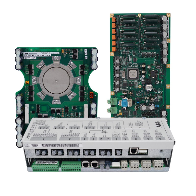
The FS450R12KE3/AGDR-71CS is a high-power IGBT (Insulated Gate Bipolar Transistor) module paired with a dedicated gate driver, designed for demanding industrial applications including medium-voltage drives, regenerative inverters, and traction systems. The FS450R12KE3 component delivers a 450A current rating at 1200V, making it well-suited for high-current switching environments where thermal stability and switching precision are critical. The AGDR-71CS gate driver complements this by providing reliable gate control, short-circuit protection, and fault signaling, ensuring the IGBT operates safely within its defined parameters.
In industrial automation, high-efficiency power solutions directly influence energy consumption and operational costs. Modules like the FS450R12KE3/AGDR-71CS reduce switching losses and improve thermal management, which translates into lower energy bills and fewer heat-related failures over time. For context, comparable modules such as the ABB SD854 power supply serve similar roles in drive systems, but the FS450R12KE3/AGDR-71CS distinguishes itself through its integrated driver protection features and robust current handling capability. Suppliers like Apter Power, which operates across industrial and automotive power segments, similarly emphasize component compatibility and thermal performance as key selection criteria when evaluating modules for high-demand environments.
When selecting a power module for an industrial application, technicians should evaluate voltage and current ratings against actual load requirements, verify thermal resistance specifications relative to the cooling solution in use, and confirm compatibility with existing gate driver interfaces. Choosing an undersized or mismatched module is one of the most common sources of premature failure in switch-mode power supply systems.
Pre-Maintenance Preparation: Safety and Tools
Before touching any component of the FS450R12KE3/AGDR-71CS, implementing proper lockout/tagout (LOTO) procedures is mandatory. Isolate the system from all energy sources, discharge bus capacitors fully, and verify zero voltage with a calibrated meter before proceeding. Wear appropriate PPE throughout, including insulated gloves rated for the system voltage, safety glasses, and antistatic wrist straps to prevent electrostatic discharge damage to sensitive gate driver circuitry.
Gather the following tools before beginning any maintenance task: a true-RMS digital multimeter, an insulation resistance tester (megohmmeter), a thermal imaging camera or contact thermometer, compressed air or an ESD-safe vacuum for cleaning, isopropyl alcohol (90%+) with lint-free swabs, and a calibrated torque wrench for terminal fasteners. Having everything on hand before starting prevents mid-procedure interruptions that can introduce errors.
Always reference the manufacturer’s datasheet and application notes for the FS450R12KE3/AGDR-71CS when establishing torque values, clearance distances, and test thresholds. Build a documented maintenance schedule that defines inspection intervals—typically every 3 to 6 months under normal load conditions—so that checks occur consistently rather than only after a fault appears.
Step-by-Step Maintenance Procedures for FS450R12KE3/AGDR-71CS
A structured maintenance approach prevents the guesswork that leads to extended downtime. The procedures below follow a logical sequence—inspect first, test second, replace only what evidence supports—so technicians work efficiently and avoid introducing new faults while addressing existing ones.
Visual Inspection and Cleaning Routines
Begin every maintenance cycle with a thorough visual scan of the module housing, bus terminals, and gate driver board. Look for discoloration or burn marks that indicate thermal stress, swollen or leaking capacitors, cracked solder joints, and any signs of moisture ingress or corrosion on connector pins. Check that all terminal fasteners are secure and that no wiring insulation shows abrasion. For cleaning, use short bursts of dry compressed air to dislodge dust from heatsink fins and the driver PCB, then follow with lint-free swabs lightly dampened with 90%+ isopropyl alcohol on contact surfaces and connector pins. Allow all surfaces to dry completely before reassembly. Never use water-based cleaners or abrasive materials, as these can compromise insulation integrity and accelerate corrosion on exposed copper traces.
Electrical Testing and Performance Calibration
With the system safely re-energized under controlled conditions, use a true-RMS multimeter to verify DC bus voltage and gate drive supply rails against the values specified in the datasheet. Measure output current at known load points and compare against baseline readings recorded during commissioning—a deviation greater than 5% warrants further investigation. Use an oscilloscope to examine gate pulse waveforms at the AGDR-71CS output, confirming rise and fall times fall within specified limits, as sluggish switching indicates driver degradation or gate resistor drift. Check the fault output signal line to confirm the protection circuitry responds correctly to a simulated overcurrent event. If the module includes onboard temperature sensors, log their readings at full load and compare against thermal resistance specifications to verify the cooling solution is still performing adequately. Recalibrate any adjustable parameters—such as deadtime or soft-start ramp settings—only when measured performance deviates from design targets, using the manufacturer’s application notes as the authoritative reference.
Component Replacement and Upgrade Guidelines
Replace electrolytic capacitors on the gate driver board when capacitance measurements drop below 80% of rated value or when ESR rises significantly, typically after 5 to 7 years of continuous operation in elevated-temperature environments. Cooling fans should be replaced proactively at the manufacturer’s recommended service interval—or immediately if audible bearing noise develops—because fan failure is one of the fastest paths to thermal shutdown. When sourcing replacement parts, always match the original component’s voltage rating, capacitance, and temperature grade; substituting a lower-rated part to save cost routinely causes premature failure. For the IGBT module itself, source only from authorized distributors to avoid counterfeit components, which frequently lack the internal bonding quality of genuine parts. When integrating an upgraded gate driver version, verify compatibility with the existing IGBT’s gate charge requirements before installation, and update firmware or configuration settings as directed in the upgrade documentation to avoid mismatch faults during startup.
Troubleshooting Common Issues in Power Supply Systems
Even well-maintained modules encounter operational problems, and diagnosing them quickly limits production impact. Overheating is the most frequent issue with the FS450R12KE3/AGDR-71CS and typically stems from one of three causes: blocked heatsink airflow, degraded thermal interface material between the IGBT baseplate and heatsink, or a failing cooling fan. When onboard temperature sensors report elevated junction temperatures, shut down the system, inspect the heatsink for dust blockage, and verify that thermal paste has not dried or cracked. Reapply thermal compound if the existing layer shows separation or discoloration.
Voltage fluctuations at the output usually point to gate driver issues or degraded DC bus capacitance. Check the AGDR-71CS fault output first—an active fault signal narrows the cause immediately. If no fault is flagged, measure bus capacitor ESR and compare against rated values. A significant ESR increase causes ripple voltage to rise, which the module cannot fully suppress. For failure-to-start conditions in switch-mode power supply applications, verify gate drive supply voltages are within tolerance before assuming the IGBT is faulty; a missing or low gate supply rail is a common and easily overlooked cause.
Use the following diagnostic sequence to work through any fault systematically: confirm input power integrity, read all fault codes from the driver board, measure gate and bus supply voltages, inspect waveforms at the gate output, then assess thermal conditions. Following this order prevents misdiagnosis and avoids unnecessary component replacement.
Best Practices for Long-Term Performance and Efficiency
Sustaining peak performance from the FS450R12KE3/AGDR-71CS over its full service life depends on consistent environmental controls, systematic monitoring, and thorough documentation. Keep the installation environment within the module’s specified temperature and humidity ranges, and ensure enclosure ventilation is never obstructed by cable routing or adjacent equipment. Installing particulate filters on cabinet air inlets reduces heatsink fouling between maintenance cycles, directly extending the intervals between deep cleaning procedures.
Continuous monitoring through the AGDR-71CS fault output and onboard temperature sensors provides early warning before a developing issue escalates into a failure. Log thermal readings, output current, and gate supply voltages at regular intervals and trend them over time—gradual drift in any parameter signals aging components before they reach a failure threshold. Pair this data with a structured maintenance log that records every inspection, test result, and replacement, creating a traceable history that accelerates future diagnosis.
Proactive maintenance is ultimately a cost-reduction strategy. Replacing a capacitor or fan on a scheduled basis costs a fraction of an emergency shutdown caused by thermal runaway. For high-efficiency power solutions operating in demanding industrial environments, the discipline of scheduled upkeep, environmental control, and data-driven monitoring is what separates modules that reach their design lifespan from those that fail prematurely and disrupt production.
Maximizing FS450R12KE3/AGDR-71CS Lifespan Through Proactive Maintenance
Maintaining the FS450R12KE3/AGDR-71CS is not a one-time task but an ongoing commitment that directly determines how reliably your industrial systems perform. Throughout this guide, we have covered the essential building blocks of effective upkeep: establishing safe pre-maintenance conditions with proper LOTO procedures, conducting systematic visual inspections and electrical tests, replacing worn components before they cause failures, and applying structured diagnostic sequences when problems arise.
The troubleshooting strategies and best practices outlined here give technicians a clear framework for addressing the most common failure modes—overheating, voltage irregularities, and driver faults—without resorting to guesswork. Equally important is the discipline of logging every inspection and test result, turning routine maintenance into a data-driven process that catches degradation early.
Investing time in proactive maintenance pays dividends that reactive repairs never can. A scheduled capacitor replacement or a timely fan swap costs far less than an emergency shutdown that halts an entire production line. By applying the procedures and practices in this guide consistently, technicians can extend the operational lifespan of the FS450R12KE3/AGDR-71CS, reduce energy costs through sustained efficiency, and build the kind of system reliability that industrial operations depend on for long-term success.